How to Integrate 3D Elements into Video Footage – Part I

Have you ever wondered what it takes to seamlessly blend a 3D model into a previously recorded video? Let’s dive into the industry’s most common techniques.
Nowadays, when you watch a movie involving creatures, elves, or superheroes, there’s always a mix of live-action with animation. You can be sure that the post production team worked meticulously to integrate 3D elements into the scene.
The purpose is to make 3D characters act like flesh-and-blood actors. To accomplish that, the work done in compositing is critical and requires solid knowledge and practice to match the colors and lighting environments.
Post-production is just the last link in the chain. Before that, there are other preliminary steps to ensure you are setting your project up for success:
- Video clip analysis, broken down to micro activities. The imported clips can be pre-edited by color correction, lens distortion calibration when needed, and so on.
- Video clip export to external software. Here is the core of the work! There are several market solutions, and we’ll be focusing on PFTrack by The Pixel Farm.
- Maya creation scene, which takes the work done in PFTrack and prepares the final sequence.
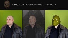
In the photo above—from the movie Life of Pi—the intention is to capture a real sequence and composite it over a digital background. They take advantage of a blue screen, but look at the presence of those red crosses.
These are called tracking markers. But what is the purpose of these indicators?
Why use Tracking Markers?
There are different applications in filmmaking and digital compositing. Tracking markers work as indicators for your real camera on the shooting stage. If it’s true that static scenes don’t need tracking, that becomes vital for animated shots.
Simply put, the goal is to record the real camera movement and transfer it to a virtual camera—hence the term camera tracking.
Also, match moving is another related word to say: “extract camera motion information to match a real footage.”
Although the purpose is the same, we can have several scenarios used in camera tracking. Let’s mention just two examples.
- In the previous Life of Pi shot, the actors are real, while the background is entirely CGI and added in comp.
- There are situations where props are digital—coming from external 3D software—and the whole scene is real.
In both situations, we cannot integrate live-action with 3D rendered sequences without a correct camera tracking. Anyway, in the rest of the episode, we’ll introduce 3D elements in a real footage.
PFTrack for Camera Tracking
As mentioned at the beginning, we need software for the tracking process. Nowadays, camera tracking is popular and seamlessly integrated into several software solutions. After Effects also has that feature built-in.
However, we’ll be using a dedicated tool called PFTrack. Here is what it looks like once loaded up, with a pre-imported scene.
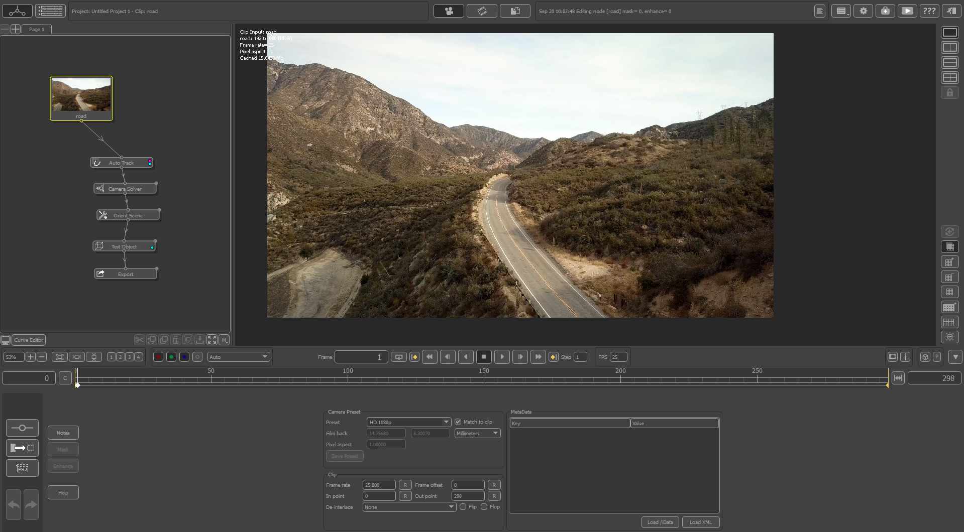
It is a node-based software with many features. The main area shows the pre-loaded footage and the possibility to scroll horizontally through the timeline.
The left panel contains the nodes involved—we’ll dive into some of the nodes later and show how nodes keep the work organized, clean, and easy to edit.
Finally, the bottom panel is specific to each currently selected node. We have dedicated options that are extremely useful while tracking the video. Nonetheless, remember that we are not explaining PFTrack itself, but we’ll try to focus on specific functionalities for our purpose.
A Feature-rich Tool
Before getting to the nitty gritty, I would like to dig a short digression on this software’s the important features. To look at the full documentation in-depth, please follow this link.
The node panel, organized by tabs, groups the nodes by their function. Consequently, we have the following categories:
- Tracking
- Solving
- Distorsion
- Geometry
- Photo
- Z-Depth
- Spherical
- Stereo
- Export
- Utilities
- Python
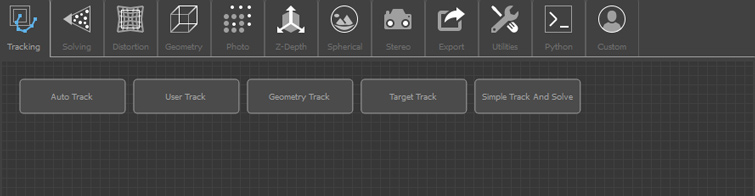
We’ll explain the most relevant categories.
Tracking, as the word suggests, allows reading the clip by extracting information about certain features. Features are elements being tracked through the entire sequence. We can use either Auto or User tracking—the latter for manually adding custom points in space.
Solving, particularly the camera solver, takes the features from the tracking to build the virtual camera motion in the scene.
Distortion allows you to work with a camera lens and deal with eventual barrel/pincushion effects in the source video.
Geometry has a significant impact on the 3D preview result. You can add test objects and see whether the tracking works or not.
Export saves the result to many 3D packages like Maya, 3DS Max, After Effects, etc. It records the frames for the camera and relevant features in the scene.
Finally, I found the Utility to be a helpful tab, if not “mandatory,” for a few tasks. Sometimes PFTrack cannot correctly detect the focal length. Thus the Estimate Focal feature comes in handy. On other occasions, you want to orient the axis to match a surface—imagine a 3D object placed on a table. In this last case, the Orient scene is what we need.
First Steps
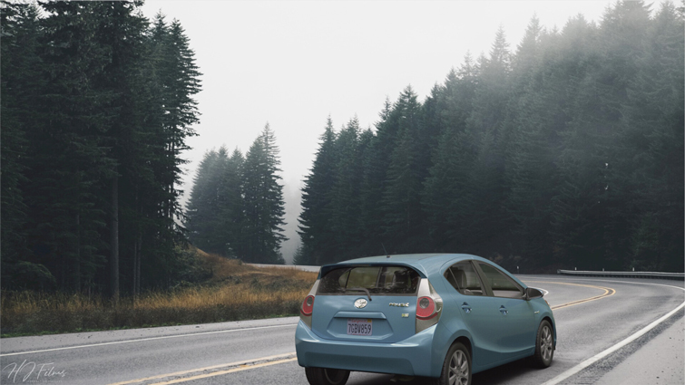
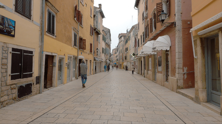
We’ll be using footage from the Shutterstock library that you can find here. The first thing to do is import the clip into PFTrack as an image sequence. After that, you are ready to start the fun part!
Most of the time, thanks to top-notch algorithms, PFTrack can analyze the video and estimate the proper camera focal length. Nonetheless, you can always help PFTrack refine the result by using the Estimate Focal Node, like in the following case. This is a manual operation where you have to estimate the proper perspective.
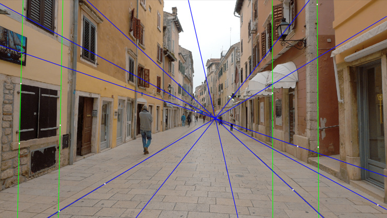
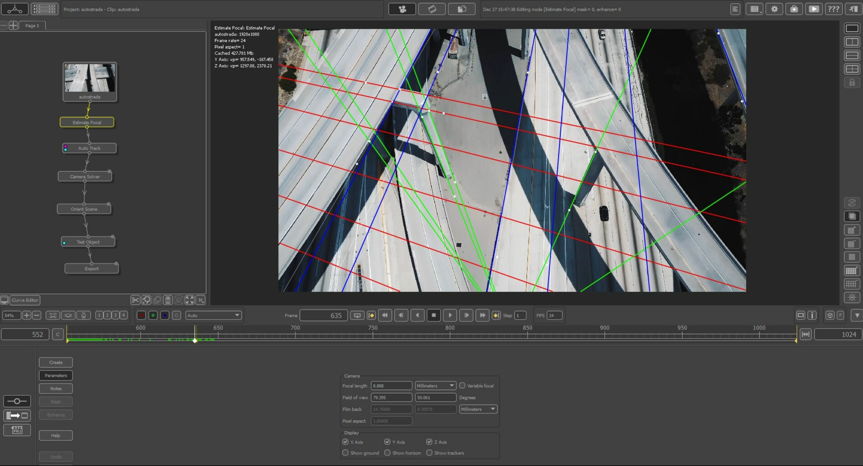
Two axes—Y and Z—are sufficient to reveal the vanishing point of the frame. We could have ignored it in this case because PFTrack does an excellent job, but look at the next shot I made for a commissioned work.
Because of the perspective from the top, we have to give PFTrack more data to compute. In particular, I used all three axes in this case. See how the green lines follow the pillars.
Since PFTrack is a node-based software, we’ll present the list of the nodes we’ll use during this presentation.
The Estimate Focal node has already been described. Let’s move on.
Auto vs. User Tracking
The Auto and User Track nodes extract relevant features from the video clip.
While the former relies on automatic operations by video processing, the latter requires user intervention. Depending on your goals, you could only use the auto tracking feature. Conversely, you might be asked to track other areas of your video manually for specific tasks.
In the following process, PFTrack picks up some features—the yellow dots—and tries to keep them stable during the video playback.
In the User Tracking, we’ll decide which trackers to insert. Here are a few general guidelines to follow:
- Locate your markers in areas of the video with strong contrast, such as darker pixels surrounded by brighter ones.
- If you can physically reach the filming location, put physical markers in strategic areas where you want to insert your 3D model.
- In PFTrack, you can adjust the brightness, contrast, and other parameters of your video to make some features pop up.
In our example, we introduced from 12 to 17 user tracks along the pavement, on the wall, and in other helpful areas.
Note that we changed the brightness and contrast of the original shot so it will track better.

Camera Solving
You are ready to estimate the virtual camera movement by the previous features.
The Camera Solver node accomplishes this task. The solving keeps track of how well a projected position corresponds to the 2D tracker location.
Use the “Solve All” action for this task.
For a specific frame:
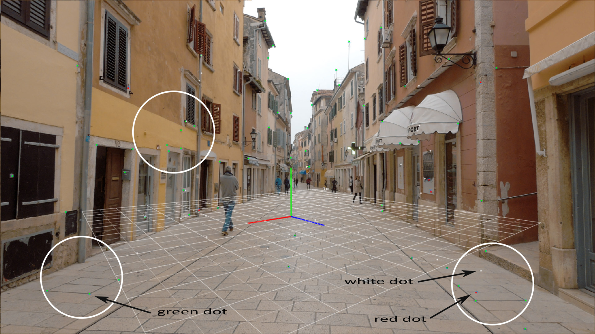
- A green dot indicates that the projection is good.
- A white dot specifies that the projection is not active now, but it will be in other frames.
- Meanwhile, a red dot is a sign that the projection here doesn’t work well.
An in-between green and red is orange, meaning a projection error of fewer than two pixels but more than one.
When a feature is red, it’s not solved well, and the projection error is more than two pixels. The projection error is the difference between the tracker path position and the projection of the 3D tracker point.
However, there are several ways to reduce projection errors.
Our current Error Graph shows how each feature behaves during the clip. Cut high peaks because they influence the average projection, causing inaccuracy and camera instability issues at specific frames.
With the trim tool, we can cut errors.
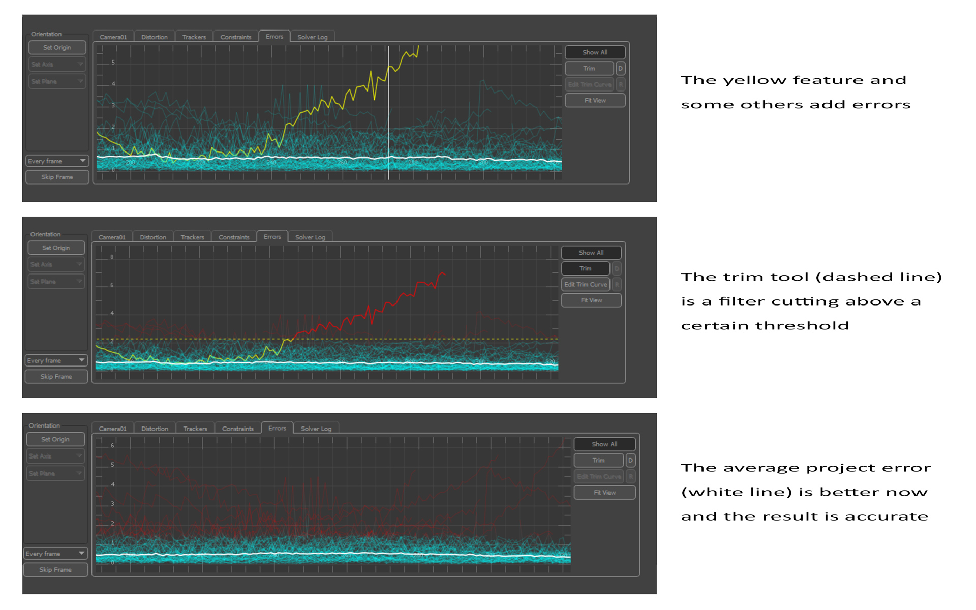
The goal is to make the white line—the average projection error—as stable as possible and towards the 0 value. That way, the result appears accurate and smooth.
If a feature causes too many problems, you can deactivate it from the “Trackers” tab of the Camera Solver node and recalculate.
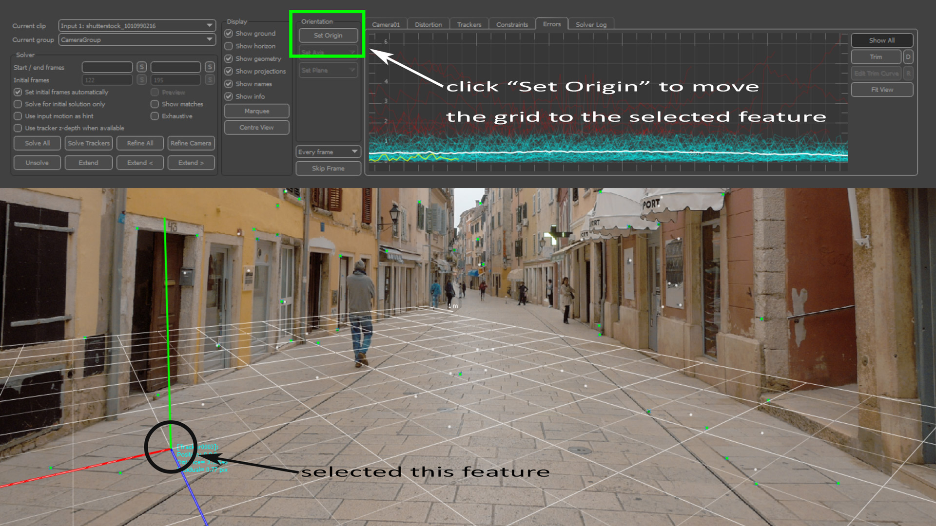
You can also locate the origin of the coordinate system to a specific feature.
To do that:
- Select a feature—green dot.
- Click on the “Set Origin” tab of the Camera Solver node.

Orienting the scene
So far, so good! The previously selected feature is just an example. You can take any feature, as long as it works well. The purpose is to give the scene the proper orientation from the camera’s point of view.
We could focus on a region where to put some 3D content—like the pavement—but you can also orient the grid in relation to the main street.
As you can see, the grid has the wrong orientation. Let’s fix it!
The Orient Scene node controls the grid’s translation, rotation, and scaling. It also has the “Set Origin” functionality for the Camera Solver node.
To make the orientation work, we select all the three trackers on the left and set an X-Z plane. This action orients the grid so that it is aligned with the pavement.
If the trackers are accurate, the grid should lie on the pavement. We only have to manually orient the grid along the Y axis (vertical) to have everything lined up.
Remember that you can extend the grid to cover more of the video clip.
Testing Objects
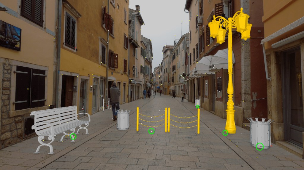
Now that the grid is aligned, we can import a few 3D models into the scene and test the tracking quality.
For this purpose, we import simple objects and locate them in specific parts of the clip.
The Test Object node has a series of simple 3D assets to import into the scene. In our case, we use custom props.
One quick note. While positioning 3D objects, consider snapping them to the calculated 3D points. That way, you’re sure they stick to the surface.
In more complex examples, you’ll need specific trackers where the surface changes direction or altitude. Imagine animating a car along a bumpy road. Without specific trackers, we can’t estimate the slope. Thus, the tracking doesn’t work.
In our example, the surface is relatively uniform and approximately flat—despite a few slight variations. So, a good scene orientation with the previous 3D points is more than sufficient.
These are the objects snapped to specific 3D points.
From the previous image, we clearly used a few strategic features to position our 3D objects. If you want to track objects at different heights—like on a doorstep, for instance—you have to:
- Add trackers on the doorstep corners.
- Build a rough parallelepiped approximating the doorstep.
- Position your 3D object on the top of the 3D parallelepiped.
That allows you to be precise on the height.
Let’s see how the clip in action!
The previous video is to check if we worked well. It doesn’t include any light information, textures, shadows, etc.
From PFTrack to Maya
As the last step inside of PFTrack, the export plays a vital role.
The Export node allows you to prepare the scene in different file formats and the file path. I typically use Autodesk Maya for the render, so let’s choose any Maya exporter. Alternatively, there is the FBX, 3DS Max options, etc.
That being said, you’ve pretty much finished with the settings! You’re well on your way to integrate your first 3D element into video footage.
Apart from the list of objects to be exported, which I keep by default, you can click on “Export Scene.”
When you open the scene in Maya, this is what you have
As you can see, we don’t have to worry about the camera animation. As the camera moves, the 3D objects maintain their position. However, if needed, you can refine the alignment of some 3D objects to perfectly match your video.
At this point, you are ready to texture and light your scene!
This is the end of the first part of this series.
You learned how to use camera tracking by adding 3D meshes to a real video clip. At this point, you should be able to integrate your 3D models into your favorite video sequence.
In the next installment, we’ll explore these areas of 3D into video integration:
- 3D object animation in a video clip.
- 3D lighting and rendering to integrate 3D objects in the video sequence.
- Techniques and tips to make the integration between 3D and video clips more believable.
And much more!
Anyway, if you like this article, I invite you to follow me on my Linkedin page.
New to working with 3D assets and models? Check out these articles:
- Creating an ACES Workflow for Realistic Lighting with 3D
- Improve Render Quality with Layer Composition in After Effects
- From Call of Duty Fan Edits to Music Videos for Russ: An Interview with 3D Artist Vollut
- Unlock the Power of 3D in After Effects with Helium
- How to Create Real 3D Terrain in Blender (Without Plugins)